In 2004, ARM announced its newest generation of licensable cores, called the “Cortex” family. Cortex cores span a wide range of performance levels, with Cortex M-series cores at the low end, Cortex R-series cores providing mid-range performance, and the Cortex A-series applications processors offering the highest performance. The first Cortex core to be announced was the Cortex-M3, and since then ARM has announced several others, including the Cortex-A8 and A9, the Cortex-M1, and the Cortex-R4.
The Cortex-R4 targets moderately demanding applications such as hard disk drives, inkjet printers, automotive safety systems, and wireless modems. It is marketed as a higher-performance replacement for the older ARM9E core. BDTI recently completed a benchmark analysis of the ARM Cortex-R4 core and is now releasing the first independent signal processing benchmark results for this processor. In this article, we’ll take a look at its benchmark results and compare its performance to that of other ARM cores (including the ARM11, another moderate-performance core) and selected competitors.
Table 1 summarizes key attributes of selected ARM processor cores.
|
|
ARM9E |
ARM11 |
Cortex-R4 |
Cortex-A8 w/NEON* |
|
Typical clock rate* |
265 MHz (130 nm) |
335 MHz (130 nm) |
375 MHz (90 nm) |
450 MHz–1100 MHz (65 nm) |
|
Instruction sets |
ARMv5E, Thumb |
ARMv6, Thumb, Thumb2 |
ARMv7, Thumb, |
ARMv7, Thumb, |
|
Issue width |
Single issue |
Single issue |
Dual issue |
Dual issue (superscalar) |
|
Pipeline stages |
5 |
8 |
8 |
13 + 10 (NEON) |
|
DSP/media instructions |
Minor |
Minor |
Minor |
Extensive (NEON) |
|
Per-cycle multiply-accumulate throughput (fixed-point) |
1 × 32-bit 1 × 16-bit |
1 × 32-bit 2 × 16-bit |
1 × 32-bit 2 × 16-bit
|
2 × 32-bit 4 × 16-bit 8 × 8-bit Float: 2 × 32-bit |
|
Data bus |
32-bit |
64-bit |
64-bit |
64-/128-bit |
|
Branch prediction |
No |
Yes |
Yes |
Yes |
Table 1. Characteristics of selected ARM cores.
*Clock speed data provided by ARM, not verified by BDTI. Clock speeds for ARM9E and ARM11 are worst-case speeds in a TSMC CL013G process and ARM Artisan SAGE-X library. Clock speed for Cortex-R4 is worst-case for a 90 nm CLN90G Artisan Advantage implementation. High-end clock speed for Cortex-A8 is based on a custom implementation.
As shown in Table 1, the Cortex-R4 is a superscalar core that can issue and execute up to two instructions per cycle. Like the Cortex-A8, it supports the ARMv7 instruction set architecture and the Thumb2 compressed instruction set, but the Cortex-R4 does not support the NEON signal processing extensions. As a result, its signal processing capabilities and features are much more limited than those of the Cortex-A8.
The Cortex-R4 as a Signal Processing Engine
The Cortex-R4 targets applications that include moderate signal processing requirements, and the core includes hardware and instructions to help improve its performance on this type of processing. For example, the Cortex-R4 supports SIMD (single instruction, multiple data) instructions that enable it to perform two 16-bit multiply-accumulate operations (MACs) per cycle; MAC operations are heavily used in many common signal processing algorithms, such as filters and FFTs.
To assess the Cortex-R4’s signal processing capabilities and compare its performance to that of other processors, BDTI benchmarked the Cortex-R4 using the BDTI DSP Kernel Benchmarks, a suite of 12 key DSP algorithms such as FIR filters, FFTs, and a Viterbi decoder. These benchmarks are hand-optimized for each processor, typically in assembly language, and verified by BDTI. The BDTI DSP Kernel benchmarks have been implemented on a wide variety of processor cores and chips, providing a range of comparison data for evaluating new processors.
BDTI uses processors’ results on the DSP Kernel Benchmarks to generate an overall signal processing speed metric, the BDTImark2000. (When the benchmark performance is verified using a simulator rather than hardware, this metric is called the BDTIsimMark2000.) The BDTImark2000 metric combines the number of cycles required to execute each benchmark with the processor’s instruction cycle rate (i.e., its clock speed) to determine the amount of time the processor requires to execute the benchmarks. For off-the-shelf chips, we use the fastest clock speed at which the chip is currently shipping. For licensable cores, the clock speed depends on how the core is fabricated. To enable apples-to-apples comparisons, BDTI typically uses clock speeds for their cores fabbed in a TSCM 130 nm process, under worst-case conditions. ARM has not reported this data for all of its cores, so BDTI has used alternate clock speeds in some cases, as noted in the table above.
In Figure 1, we present BDTIsimMark2000 cores for selected ARM cores, alongside BDTImark2000 scores for two off-the-shelf DSP processor chips for comparison.
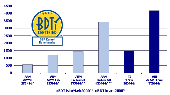
* TSMC CL013G, Artisan SAGE-X, worst-case conditions
** 90 nm, non-BDTI conditions, clock speed not BDTI certified
*** Estimated clock speed for Cortex-A8 in TI OMAP3430 implementation, clock speed not BDTI certified
Figure 1. BDTImark2000 scores for selected cores and chips. The BDTImark2000 is a composite DSP speed metric based on processors’ results on the BDTI DSP Kernel Benchmarks. A higher score indicates a faster processor. ARM has not provided clock speeds for the Cortex-R4 and Cortex-A8 that conform to BDTI’s uniform conditions for cores; therefore, the results for these two cores should not be compared to results for non-ARM cores
As shown in Figure 1, the Cortex-R4 and ARM11 have similar signal processing performance. (For a full analysis of the ARM11’s signal processing performance, see “Can the ARM11 Handle DSP?”) The Cortex-R4 is not intended to replace the ARM11; rather, ARM positions the Cortex-R4 as a higher-performance replacement for the ARM9E. Compared to that processor, the Cortex-R4 is nearly three times as fast. Some of the speed increase is due to the Cortex-R4’s more powerful architecture (we’ll discuss this more later), and some is due to its faster clock speed.
At the clock speeds shown above, the Cortex-R4’s signal processing speed is similar to that of the Texas Instruments TMS320C55x, a widely used, mid-range DSP chip. At this level of performance, the Cortex-R4 may be able to subsume the processing typically allocated to a low-cost DSP processor. At 450 MHz, the Cortex-A8 with NEON signal processing extensions is more than twice as fast as the 375 MHz Cortex-R4. (The 450 MHz clock speed used here to calculate benchmark results for the Cortex-A8 is the estimated speed of the core as fabricated in Texas Instruments’ OMAP3410 chip.)
From the data presented in Figure 1, it’s clear the clock rate accounts for only part of the signal processing speed differences among processors. The other factor is the processors’ architectural “power”—that is, how much work each processor can accomplish in each clock cycle. In the next section, we’ll look at some of the architectural differences that contribute to the performance numbers shown above.
Behind the Benchmarks
To evaluate and compare processors’ architectural strengths and weaknesses, BDTI measures the number of instruction cycles required to execute each of the twelve benchmarks. Cycle counts don’t directly assess a processor’s signal processing speed (because speed also depends on clock rate) but they do provide a comparison of the relative power of the architecture. The lower the cycle count needed to execute a given amount of work, the more powerful the architecture.
Of course, processors that can execute the benchmarks in fewer cycles (and are therefore more powerful) may require more silicon area than less-powerful processors, or they may consume more energy. Furthermore, processor architects sometimes trade off architectural power for clock speed, so it’s important not to assume that greater architectural power will necessarily yield a faster processor.
In Figure 2, we present the BDTIsimMark2000/MHz scores for selected processor cores and chips. This metric evaluates per-cycle throughput on optimized signal processing kernels, and is based on processors’ results on the BDTI DSP Kernel Benchmarks.
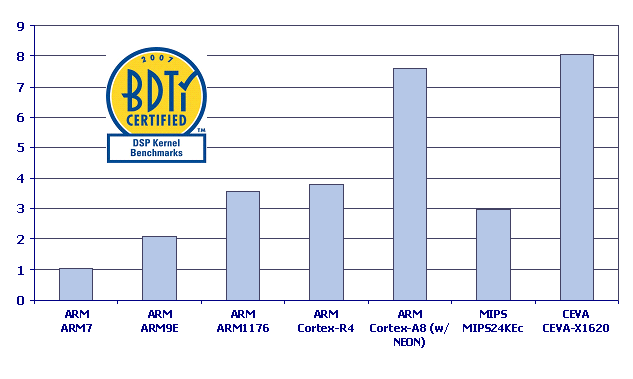
Figure 2: BDTIsimMark2000/MHz scores for selected processor cores.
As shown in Figure 2, the Cortex-R4 has roughly the same cycle-count efficiency as the ARM11. This may seem surprising since the Cortex-R4 is superscalar and the ARM11 is not. However, Cortex-R4’s dual-issue capability is quite limited. For example, although it can execute an add or subtract operation in parallel with a load or store, it can’t execute a MAC instruction in parallel with anything else. As a result, its signal processing throughput is only slightly higher than that of the ARM11.
The Cortex-R4 does have nearly twice the per-cycle signal processing throughput of the ARM9E, which is a single-MAC, single-issue core with very limited parallelism. The Cortex-R4 has twice the data bandwidth of the ARM9E and provides a number of SIMD arithmetic instructions, which the ARM9E lacks.
Compared to the Cortex-A8 with NEON, the Cortex-R4 has much lower per-cycle signal processing throughput. NEON increases the parallelism of many SIMD arithmetic operations from two to four (for example, the Cortex-A8 with NEON can perform four 16-bit multiplies in parallel, while the Cortex-R4 can do only two).
For comparison purposes, we’ve also included results for two licensable cores from other vendors: the MIPS 24KEc and the CEVA X1620. The 24KEc is a 32-bit general-purpose processor core with DSP-oriented instruction set extensions; the X1620 is a 16-bit DSP processor core. As shown in Figure 2, the
Achieving Maximum Performance
In evaluating processors, speed isn’t everything—area, power consumption, ease of programming, and application development infrastructure may be just as important. Nonetheless, it’s essential to make sure that the processor has the minimum speed needed to meet the application requirements. The benchmark results we’ve presented here should help system designers understand the relative signal processing capabilities of the Cortex-R4 core and determine whether it has sufficient speed for their application. However, we have one additional caveat. Achieving the performance results we’ve presented was not a trivial undertaking; each of the benchmarks was painstakingly hand-optimized in assembly language to squeeze the maximum performance from each processor.
Cortex-R4 users requiring maximum performance will need to perform a similar level of optimization, a process that can be more challenging than on previous-generation ARM cores due to the Cortex-R4’s SIMD capabilities, superscalar execution, and deeper pipeline. Later in this article, we’ll describe some of the optimization techniques we’ve used for implementing signal processing algorithms on the Cortex-R4.
Optimizing Signal Processing Software for the ARM Cortex-R4
Applications that involve real-time signal processing often have fairly stringent performance targets in terms of speed, energy efficiency, or memory use. As a result, engineers developing signal processing software often must carefully optimize their code to meet these constraints. Appropriate optimization strategies depend on the metric being optimized (e.g., speed, energy, memory), the target processor architecture, and the specifics of the algorithm.
Cortex-R4 Instruction Set
As we discussed earlier, the Cortex-R4 core implements the ARMv7 instruction set architecture. It uses an eight-stage pipeline and can execute up to two instructions per cycle. The core supports the Thumb2 compressed instruction set, though most of BDTI’s signal processing benchmark code is implemented using standard ARM instructions because of their greater computational power and flexibility. (Signal processing algorithms are typically optimized for maximum speed rather than minimum memory use, though memory usage is often a secondary optimization goal.)
On the Cortex-R4, the instruction set is fairly simple and straightforward, and most of it will be familiar to engineers who have worked with other ARM cores, particularly the ARM11. Compared to the earlier ARM9E core, however, the Cortex-R4 is noticeably more complex to program due to its superscalar architecture and deeper pipeline (8 stages vs. 5). And, unlike the ARM9E, the Cortex-R4 supports a range of SIMD (single-instruction, multiple-data) instructions, which improve its signal processing performance, but often require the use of different algorithms, different data organization, and different optimization strategies compared to approaches that worked well with earlier ARM cores.
The Cortex-R4 is in some ways similar to the ARM11, which supports a similar range of SIMD operations and also has an eight-stage pipeline. One difference between the two cores is that the Cortex-R4 is a dual-issue superscalar machine while the ARM11 is a single-issue machine. In some cases, this will mean that different optimization strategies are needed to ensure that instructions dual-issue as often as possible. But in many tight inner loops, the two cores may end up using very similar code. This is because of a key limitation on the Cortex-R4’s dual-issue capabilities: it cannot execute multiply-accumulate (MAC) operations in parallel with a load, and it cannot use its maximum load bandwidth (64 bits) in parallel with any other operation. As a result, in signal processing inner loops that require maximum MAC throughput or maximum memory bandwidth, the Cortex-R4 is often limited to executing a single instruction at a time.
Multi-Level Optimization
The benchmark results we presented earlier are the result of careful hand-optimization of assembly code. But rather than diving right into assembly-level optimization, we will take a hierarchical, top-down approach: We will start with a simple C implementation of the filter, then create compiler-friendly code, then evaluate whether (and where) assembly-level optimizations are needed, and finally optimize the assembly code.
We’ll describe some of the high-level and assembly-level optimization techniques we’ve found to be successful on the Cortex-R4. We will use an FIR filter as an illustrative example since it’s a common and familiar signal-processing algorithm and is amenable to a number of optimization strategies on the Cortex-R4. The optimization techniques we will cover include:
- Helping the compiler recognize optimization opportunities
- Choosing algorithms that can take advantage of the Cortex-R4’s SIMD capabilities
- Using software pipelining and loop unrolling to conceal instruction latencies and reduce stalls
- Reducing memory accesses
We’ll start with a simple C implementation of the FIR filter and show a progression of optimization techniques.
The FIR Filter: A Simple C Implementation
If we implement a 40-sample, 16-tap FIR filter in C without making any attempt to optimize it, the code might look like this:
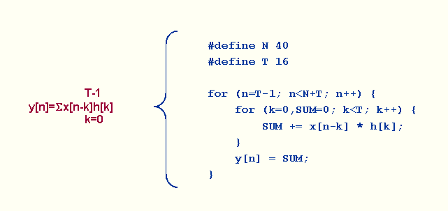
Figure 3: Simple C implementation of an FIR filter kernel
On the left side of Figure 3 we show the analytical expression for the FIR filter algorithm, and on the right side we show a simple mapping of the FIR filter to a C implementation. Notice that the mapping produces two nested “for” loops—the inner loop runs over all of the taps (T), and the outer loop runs over all of the input samples (N). (We should also point out that this figure does not show the entire FIR filter implementation; for example, we are not maintaining the delay line here.) Like many (though not all) signal processing algorithms, the FIR filter makes heavy use of multiply-accumulate (MAC) operations.
For this implementation, we’re using 16-bit data rather than 32-bit data—although the Cortex-R4 supports both data types, 16 bits is more commonly used in embedded signal processing, and the Cortex-R4’s maximum MAC throughput is achieved with 16-bit data.
When we compile this code for the Cortex-R4, the inner loop assembly code looks like this:
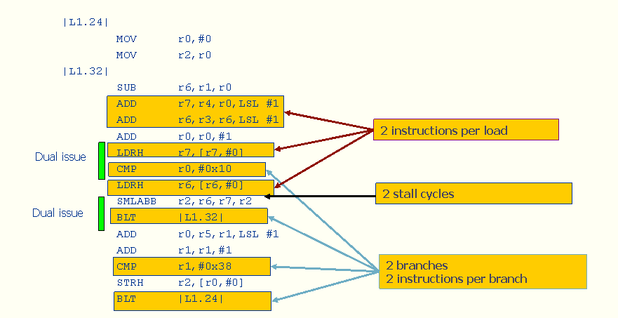
Figure 4: Result of compiling simple C FIR filter implementation on Cortex-R4
In this case, the compiled code does make use of the dual issue capabilities of the Cortex-R4 in two places in the inner loop. However, our naive C implementation doesn’t give the compiler many hints about how to generate an effective assembly implementation, and the compiler doesn’t generate code that is as efficient as it could be.
The cycle count for this implementation is 9 cycles per iteration of the inner loop—which is equivalent to 0.11 taps per cycle. In an FIR filter, each tap requires one MAC and two data loads. Given that the Cortex-R4 can perform two MACs per cycle (with an additional cycle or two for data loads) we’d expect much better throughput than what we’ve achieved here. Therefore, our first step is to look for places in the algorithm where the processor could be doing work more efficiently.
On the Cortex-R4, the condition for a branch can be set by arithmetic operations (such as add and subtract). We have to do some additions to update the loop counters anyway, so this is a good place to modify the C code to help the compiler generate a more efficient implementation. In other words, we have instructions for updating the loop counters such as ADD r0,r0,#1 for the inner loop. But we can omit the CMP r0, #0x10 instruction if we use a “count down” optimization. In this case, we no longer need to explicitly do a comparison with 0, because the BNE—branch not equal—instruction will automatically take care of that case.
The Cortex-R4’s instruction set includes load instructions with pointer updates, but the compiler did not use these instructions. Instead, it used separate instructions for loads and pointer updates. Rewriting the code can guide the compiler to choose the more efficient instructions.
There are several other inefficiencies in the compiler output. For example, the code has a two-cycle stall in the middle of it. That’s because loads have two-cycle latencies, and the MAC instruction needs data available in the register one cycle prior to issuing the MAC. Furthermore, although the Cortex-R4 has 64 bits of data bandwidth, the LDRH (load half-word) only uses 16 bits; thus we’re using more load/store instructions than we really need. And finally, the compiler did not recognize the opportunity to use SIMD multiplication.
Giving the Compiler a Hand
Rewriting the C implementation of the filter can help the compiler recognize more opportunities for optimization. In Figure 5, we’ve re-written the C code in a way that’s more compiler friendly.
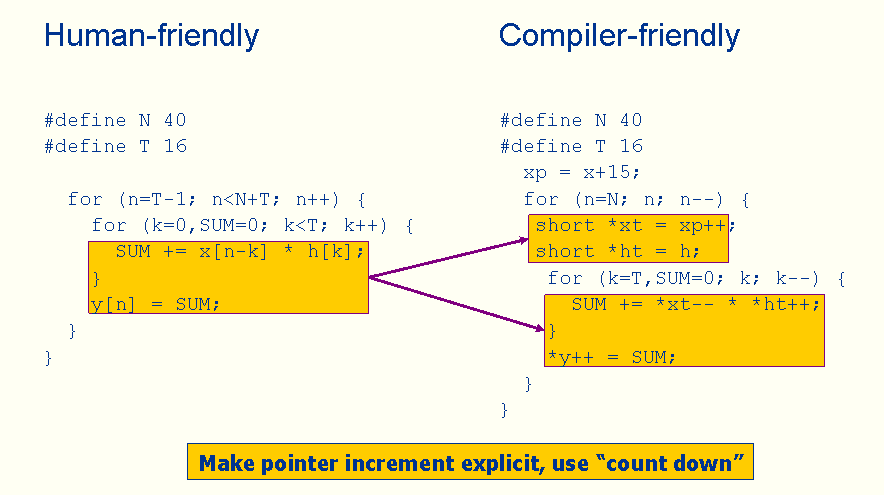
Figure 5. A more compiler-friendly FIR Filter
In the new version, we’re using the “count down” strategy instead of counting up. And we’re using explicit pointer increments to encourage the Cortex-R4 compiler to choose the load instructions with pointer updates. The resulting assembly output is shown in Figure 6.
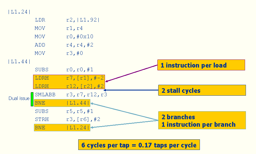
Figure 6: Output from “compiler-friendly” FIR filter on Cortex-R4
This implementation requires 0.17 taps per cycle, which is a lot better than the earlier implementation—1.5X better to be exact. Because of our changes, the compiler chose the “LDRH” instruction that automatically updates the base register pointers (R1 and R2) instead of issuing a separate ADD instruction. And as we’d hoped, the compiler used the BNE instruction for the loop counter and removed the CMP instruction, thus further reducing the cycle count.
But we’re still not really taking the Cortex-R4’s pipeline into account, nor are we taking advantage of the Cortex-R4’s ability to do SIMD operations, which are crucial to the Cortex-R4’s FIR filter performance. Furthermore, we are still using only 16 bits of data bandwidth.
Unfortunately, this is about as good as a compiler typically gets. So if we want better performance, we’re going to have to write some assembly code.
Adding SIMD
The first assembly code modification we’ll make is to modify the FIR filter inner loop to use the Cortex-R4’s SIMD dual-MAC instructions (SMLAD) and increase the size of each load from 16 bits to 64 bits (using LDRD, load double-word). This will enable significant performance benefits. As mentioned earlier, however, a key limitation of the Cortex-R4’s dual-issue capabilities is that it cannot issue a multiply instruction (or a dual-MAC) in parallel with any other instruction—so although we can modify the code to use SIMD, we cannot sustain two MACs per cycle, even with assembly-level optimizations.
The modified assembly code is shown in Figure 7.
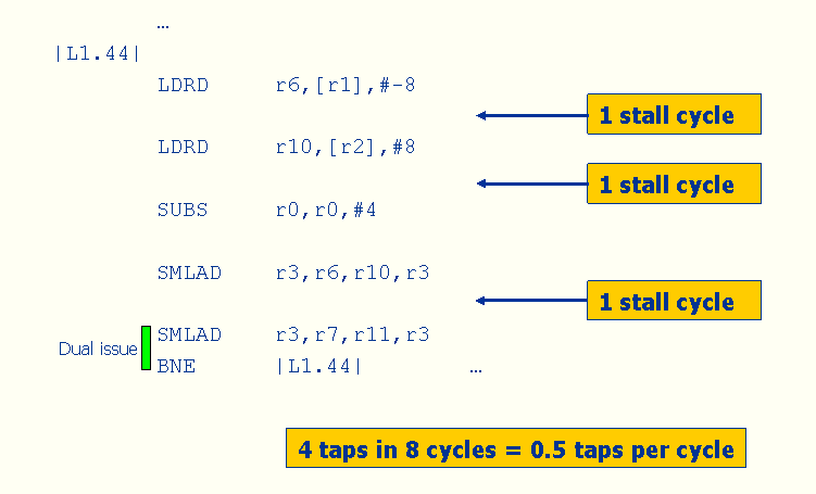
Figure 7: Adding SIMD: The Simple Approach
The resulting performance is 0.5 taps per cycle, which is about a 3X improvement over the improved compiler output. But now more than a third of the cycles in the inner loop are stalls. This happens because both the loads and the MACs have multi-cycle latencies, and the code is not currently arranged in a way that enables the processor to do useful work during those stall cycles. To get rid of the stalls, we’ll need to use software pipelining.
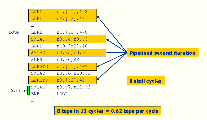
Software Pipelining, Algorithmic Transformations
Software pipelining is an optimization technique in which the assembly programmer (or compiler) re-orders instructions to eliminate stalls and allow the processor to do useful work when it would otherwise be idle.
Figure 8: Add Software Pipelining
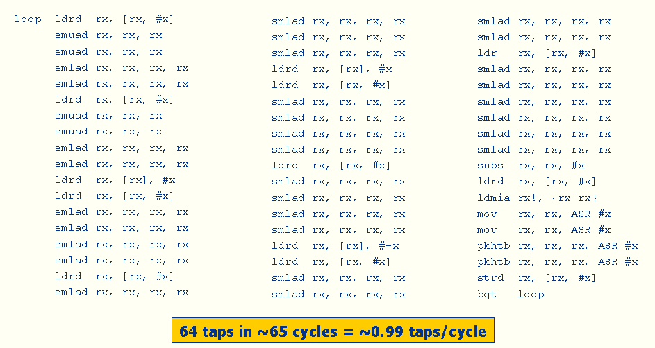
Figure 9: Fully Optimized FIR Inner Loop for Cortex-R4
In Figure 9, we show a well-optimized FIR filter inner loop that uses loop unrolling, the “zipping” optimization (commonly used in FIR filters) and careful instruction scheduling to improve performance. (Here, the register names have been replaced with “x’s” because this code is proprietary.) In this version, we’ve unrolled the outer loop four times and unrolled the inner loop completely. Unrolling the inner loop eliminates its loop overhead, while unrolling the outer loop enables the use of zipping to reduce memory accesses. That is, each of the four outputs computed in a loop iteration shares most of its operands with other outputs, so we need many fewer loads compared with the previous versions of the code.
In this version, we’ve also scheduled the instructions to avoid stalls between LDRD (load double-word) and SMLAD (dual-MAC) instructions. The resulting code is very similar to what you would see for the single-issue ARM11; there is very little opportunity for Cortex-R4 instructions to dual-issue in this loop because neither the SMLAD instructions nor the LDRD instructions can dual issue. Nevertheless, this version yields much better FIR filter throughput than what we started with—0.99 taps/cycle. But of course, this improvement didn’t come for free—it took an expert programmer about 20 hours to implement, and it requires many more instructions (and thus, more memory) than the simple implementation.
Conclusion
The Cortex-R4 provides much higher signal processing throughput of the ARM9E, but in part because of its deeper pipeline and SIMD capabilities, the Cortex-R4 is also a more challenging target for software optimization. Achieving its maximum performance will require careful optimization at several levels, and programmers will need to trade off code portability and optimization effort against processor performance. Like with all processors, the key is to become familiar with all of the instruction variants, pipeline effects, and other architecture details, and to understand the limitations of the compiler.


Add new comment